You want to flip a switch at the bottom of the stairs and have the light turn on. Then you walk up, flip the switch at the top, and turn it off. No running back down in the dark. This is the classic three-way switch setup. It sounds complicated, but it is just a different kind of circuit.
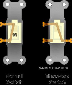
Standard switches are simple. They break or make a connection with two terminals. Open or closed. Three-way switches are different. They have three terminals. The internal mechanism connects the common terminal to either one of the two traveler terminals. You swap the path. That is how you control one light from two locations.
Зміст
The Hardware You Need
You cannot use a regular toggle switch here. You need specific components.
- Three-way switches : These look like standard switches but have three screw terminals plus a ground screw.
- 3-wire cable : This is the key. You need Romex that contains three insulated conductors (black, red, white) plus a bare ground wire. This runs between the two switches.
The Wiring Logic
The power source usually comes from the circuit breaker panel. It travels first to one of the switches, not the light fixture. This is a common point of confusion.
-
Power to Switch #1 : The hot wire (black) from the panel enters the common terminal of the first three-way switch. The neutral wire (white) from the panel connects directly to the neutral wire going to the light. It does not go through the switch. The bare ground connects to the switch’s ground screw and continues to the light.
-
Between the Switches : This is where the 3-wire cable comes in. The black and red wires in this cable are the “travelers.” They carry the current back and forth between the two switches. The white wire in this cable is used as a neutral return path or a ground, depending on the specific code era and configuration, but typically it is capped or used as a neutral if the light is near the switch. In the standard hot-switched scenario, the white wire in the 3-wire cable between switches is often used as a hot wire (re-identified with black tape) or left as a neutral depending on the exact diagram. For the basic explanation, think of the black and red wires as the active paths that change based on the switch position.
-
Switch #2 to Light : From the second switch, a standard 2-wire cable (black and white) runs to the light fixture. The hot wire from the switch connects to the light’s hot terminal. The neutral and ground connect to the fixture.
Why It Works
Imagine the current is a traveler looking for a path to the light.
- Switch A is in Position 1. Current flows out the black traveler wire.
- Switch B is in Position 2. It connects the red traveler terminal to the common terminal.
- The circuit is open. The light is off.
Now, flip Switch B.
- It connects the black traveler terminal to the common terminal.
- Current flows from Switch A’s black traveler, through Switch B’s black terminal, out the common terminal, and to the light.
- The light turns on.
Flip either switch again, and the path breaks. The light goes
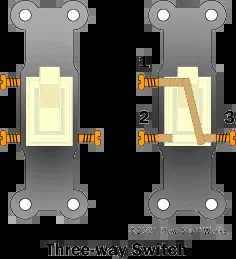
Tracing the Circuit Logic
Flip the switch up, and terminals 1 and 3 lock together. Flip it down, and the connection shifts to terminals 2 and 3. Look at the diagram. The light stays dark. Flip one switch. The circuit closes. The light turns on. Flip it again. The loop breaks. The light dies. It seems complicated until you strip away the mystery. Then it is just a simple mechanical arrangement.
Alternative Wiring Configurations
This isn’t the only way to wire three-way switches. Power could originate at the fuse box and travel to the light fixture first. From there, two switches could run in series. Or, power might enter the fixture and split into two parallel paths leading to the switches. The logic holds regardless of the physical layout.
Reverse-Engineering Existing Wiring
You are trying to figure out how a set of switches is wired in your house? You can’t just guess. You need an ohmmeter or a continuity detector. This is the only reliable way to trace what the original electrician did.
Warning: Always turn the power off at the fuse panel before probing any electrical wiring. Safety first.
Once the power is cut, the test is straightforward. If you understand the basic theory behind three-way switches, decoding the existing setup becomes trivial. It is about recognizing the pattern of connectivity.
Deepening Your Knowledge
Curiosity drives DIY. If you want to satisfy that itch, the concepts are clear now. For broader context, look into how light bulbs function, how fluorescent lamps operate, or the mechanics of the power distribution grid. Understanding how light itself works adds another layer to the puzzle. Curious about the bulbs themselves? There are specific articles on three-way light bulbs and touch-sensitive lamps too.
For practical application, check out resources like HandymanWire for detailed wiring guides or explore the specific mechanics of three-way circuits. The “magic” is just physics.